Chapter 4 - Diagnostic Test Procedures
4.1 - INTRODUCTION TO DIAGNOSTICS
Revision B Diagnostic EPROMs are for use with Kurzweil 250 and Kurzweil 250X units with Version 2.2 or earlier software installed. If the instrument you are testing has software later than Version 2.2 installed, you should test it with Revision D Diagnostics.
Revision B Diagnostic EPROMs are in 128K EPROMs. If you are testing a Kurzweil 250X, you will need Revision B Diagnostic EPROMs in 256K EPROM.
4.2 - INSTALLING DIAGNOSTIC EPROMS
1. Turn off system power 2. Open the slide chassis. 3. Remove U38 and U54 from the CPU board. Be careful when removing these EPROMs as you will be reinstalling them when the testing is complete. 4. Install U38 (Loc. 01) and U54 (Loc. 02) Diagnostic EPROMs in the empty sockets on the CPU board. NOTE: When installing the diagnostic EPROMs, be sure pin 1 is facing the rear panel. 5. Turn on system power NOTE: When the system is first turned on, the front panel LEDs may come on in an unpredictable pattern. They should all turn off after about one second. 6. The red power indicator light on the POD should be on. The front panel LCD should indicate:
K250 DIAGNOSTICS (C)
REV. B    24-JAN-85
The SELECT switch LED should be blinking on and off.
4.3 - POWER SUPPLY (POD) VOLTAGES
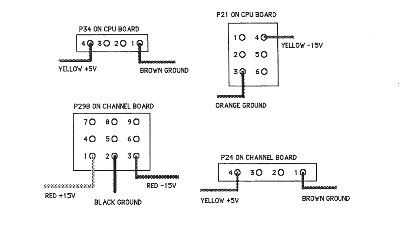
Before beginning the diagnostic test procedure, please be sure that the power supply voltages are correct. Verify the following:
- 1. The Power Supply (POD) provides:
+5 volts DC +15 volts DC -15 volts DC
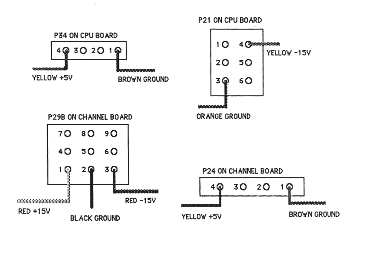
- 2. Using a VOM or DVM check the power supply voltages at the following power connectors:
4.4 - RUNNING THE DIAGNOSTIC TESTS
The Diagnostic tests check the following subsystems:
A. Front Panel assembly B. CPU board C. CGP board D. Channel board
The SELECT switch and the YES and NO switches are used to select a test and answer the prompts displayed on the LCD. When a YES or NO response is required by the diagnostic test, the YES and NO switch LEDs will blink on and off alternately. When a SELECT response is required, the SELECT switch LED will be blinking in some instances, and no LEDs will be blinking in other instances. When no LEDs are blinking, only the SELECT switch has an effect when pressed.
4.5 - FRONT PANEL TESTS
The Front Panel tests check the following subassemblies:
1. LCD 2. Control Panel LEDs 3. Control Panel switches 4. Control Panel analog to digital converter:
External Pedal 1 Feedback from Channel board mixer, group B Feedback from Channel board mixer, group A Master Tune slider Slider board voltage maximum Slider board voltage minimum External Pedal 2 Assignable Slider 3 Assignable Slider 2 Assignable Slider 1 Left Mod Lever Right Mod Lever Right POD Pedal Left POD Pedal
4.6 - LCD TEST
To run the LCD test from the initial power up display message:
1. Press SELECT 2. Answer the displayed questions by pressing the YES or NO switch on the front panel as follows:
CLR PWR FAIL CTN? Press YES AUTOTEST? Press NO RUN ALL TESTS? Press NO FRONT PANEL? Press YES ALL FP TESTS? Press YES
The LCD should now display the following:
!"#$%&'()*+,-./01234567
89:;<=>?@ABCDEFGHIJKLMNO
Press SELECT
The LCD should now display the following:
PQRSTUVWXYZ[]^_abcdefg
hijklmnopqrstuvwxyz{}><
4.7 - LED TEST
The LED test follows immediately after the LCD test by pressing SELECT. These four tests will step through in sequence automatically. To abort the LED tests, press and hold the SELECT switch.
The Front Panel LED test consists of four parts:
1. All LEDs on/off 10 times 2. One LED on at a time 3. One LED off at a time 4. Enable/disable LEDs on/off 10 times
4.8 - SWITCH TEST
After the LED test the LCD will indicate:
SWITCH TEST
PRESS ANY SWITCH
When any of the Front Panel switches is pressed, the switch number and function name will be displayed on the LCD. If the switch has an LED, the LED will blink on and off.
Press the SELECT switch to exit this test.
4.9 - ANALOG TO DIGITAL CONVERTER TEST
The ADC test will verify operation of some of the Front Panel sliders as well as the Foot Pedals and Mod Levers. The LCD display will prompt for a YES or NO switch response as follows:
A/D CONVERTER TEST
EXTERNAL PED 1? Press YES
The LCD will show the A/D reading in HEX. for External Pedal 1 the approximate readings should be:
0 0 PEDAL NOT PLUGGED INTO REAR PANEL JACK 7E PEDAL UP 0B PEDAL DOWN
Press SELECT to proceed to the next ADC test.
FEEDBACK B? Press YES
The ADC reading should be approximately 7D.
Press SELECT to proceed to the next ADC test.
FEEDBACK A? Press YES
The ADC reading should be approximately 7F.
Press SELECT to proceed to the next ADC test.
MASTER TUNE? Press YES
The ADC reading should be approximately:
14 SLIDER IN LEFTMOST POSITION 8 1 SLIDER IN CENTER POSITION ED SLIDER IN RIGHTMOST POSITION
Press SELECT to proceed to the next ADC test.
VOLTAGE MAX? Press YES
The ADC reading should be ED the same as the Master Tune rightmost position.
Press SELECT to proceed to next ADC test.
VOLTAGE MIN? Press YES
The ADC reading should be 14 the same as the Master Tune leftmost position.
Press SELECT to proceed to the next ADC test.
EXTERNAL PED 2? Press YES
The ADC readings should be approximately the same as for the External Pedal 1:
00     PEDAL NOT PLUGGED INTO REAR PANEL JACK
7E     PEDAL UP
0B     PEDAL DOWN
Press SELECT to proceed to the next ADC test.
ASSIGNABLE 3? Press YES
The ADC readings should be approximately the same as for the Master Tune slider:
14     SLIDER IN DOWN POSITION
80     SLIDER IN CENTER POSITION
ED     SLIDER IN UP POSITION
Press SELECT to proceed to the next ADC test.
ASSIGNABLE 2? Press YES
The ADC readings should be approximately the same as for the Master Tune slider:
14    SLIDER IN DOWN POSITION
80    SLIDER IN CENTER POSITION
ED    SLIDER IN UP POSITION
Press SELECT to proceed to the next ADC test.
ASSIGNABLE 1? Press YES
The ADC readings should be approximately the same as for the Master Tune slider:
14    SLIDER IN DOWN POSITION
80    SLIDER IN CENTER POSITION
ED    SLIDER IN UP POSITION
Press SELECT to proceed to the next ADC test.
LEFT MOD LEVER? Press YES
The Mod Lever ADC reading may vary since final calibration is performed during an audio test. The approximate readings should be:
80    MOD LEVER CENTERED
0A    MOD LEVER DOWN
EB    MOD LEVER UP
Press SELECT to proceed to the next ADC test.
RIGHT MOD LEVER? Press YES
The Mod Lever ADC reading may vary since final calibration is performed during an audio test. The approximate readings should be:
80    MOD LEVER CENTERED
0A    MOD LEVER DOWN
EB    MOD LEVER UP
Press SELECT to proceed to the next ADC test.
The POD foot pedals have three positions:
52    PEDAL UP
7B    PEDAL HALF WAY DOWN
A9    PEDAL DOWN
Press SELECT to proceed to the next ADC test.
LEFT PEDAL? Press YES
The left POD pedal readings should be approximately the same as the right pedal:
52    PEDAL UP
7B    PEDAL HALF WAY DOWN
A9    PEDAL DOWN
Press SELECT to exit the Front Panel Test and return to the main menu.
4.10 - CPU TESTS
Some of the CPU tests require the use of the loopback connectors provided in the Diagnostic Kit. These connectors are:
1. MIDI loopback connector 2. SYNC IN/OUT loopback connector (also used for CLICK OUT/TRIG IN) 3. Parallel Computer (PC) loopback connector
Starting with the first main menu question displayed on the Front Panel LCD, press the YES, NO or SELECT switch in response to the display prompts as follows:
- CLR PWR FAIL CNT? Press YES AUTOTEST? Press NO RUN ALL TESTS? Press NO FRONT PANEL? Press NO TEST CPU? Press YES ALL CPU TESTS? Press NO TEST CPU RAM? Press YES ALL CPU RAM? Press YES
The diagnostic will now proceed to test the main CPU random access memory (RAM). If there is an error during the test, a diagnostic error message will be displayed on the front panel LCD indicating the address of the error, the expected (good) data, and the actual (bad) data read.
RAM TEST ERR A: 1003FF <<<< THIS IS THE ADDRESS
GOOD: 55    BAD: FF
If the RAM data error occurs, the individual RAM tests may be run to determine the memory chip component number.
If there are no main RAM errors, the next LCD prompt will be:
TEST OPTIONAL RAM?
(NOTE: This RAM is standard on newer units.)
The response to this question is NO if the sequencer RAM is not installed on the CPU board. The response is YES, if the RAM is present. If the test passes the next prompt will be:
TEST INDIVIDUAL RAM?
The response to this question is NO if the previous RAM test(s) have run successfully with no error messages displayed. The response to the this question is YES, if there were errors during the previous RAM test(s). If you respond with YES, the following prompts will be displayed:
MAIN CPU RAM
TEST U33? TEST U49? TEST U32? TEST U48? TEST U31? TEST U47? TEST U30? TEST U46?
OPTIONAL CPU RAM
TEST U29? TEST U44? TEST U28? TEST U43?
TEST U26? TEST U41? TEST U25? TEST U40?
The next prompt after the RAM tests is:
TEST CPU ROM? Press YES ALL CPU ROM? Press Yes
The CHECKSUM for each EPROM will bo displayed on the LCD. The CHECKSUMs are for the following EPROMs:
U38         (DIAGNOSTIC EPROM)
U54         (DIAGNOSTIC EPROM)
U37
U53
U36
U52
U35
U51
The 8254 timers are the next CPU components checked. The outputs of the timers are Pins 10, 13 and 17. The prompt is:
INIT TIMERS? Press YES
Using an oscilloscope with probe, check for the following square waves at the IC and pin number indicated:
IC NUMBER	PIN NUMBER	SQUARE WAVE PERIOD

U68	10	200 nsec.
U68	13	400 nsec.
U68	17	600 nsec.

U69	10	800 nsec.
U69	13	1 μsec.
U69	17	2 μsec.

U87	10	3 μsec.
U87	13	4 μsec.
U87	17	5 μsec.

U88	10	6 μsec.
U88	13	7 μsec.
U88	17	8 μsec.

U106	10	9 μsec.
U106	13	25 μsec.
U106	17	50 μsec.

U107	10	75 μsec.
U107	13	100 μsec.
U107	17	125 μsec.

U118	10	150 μsec.
U118	13	175 μsec.
U118	17	200 μsec.

U119	10	225 μsec.
U119	13	250 μsec.
U119	17	500 μsec.
The next CPU test is the keyboard interface test.
TEST KEYBOARD? Press YES
KEYBOARD TEST PRESS ANY KEY
The first key on the left is numbered zero. The last key on the right is numbered 87. The keyboard is divided into two keyswitch boards. The left half of the keyboard contains keys 0 through 43. The right half of the keyboard contains keys 44 through 87. The keyboard split occurs between E4 and F4 in the center of the keyboard.
Pressing and holding down the E4 key on the keyboard will NOT sound an audible note, but will cause the front panel LCD to show:
EXAMPLE:
ATTACK       KEY 43

TOF: F0      COUNT: 1
Releasing the E4 key will cause the front panel display to show:
RELEASE      KEY: 43

TOF: 93      COUNT: 2
Press SELECT to exit the keyboard test.
The next four tests require the loopback connectors provided with the Diagnostic Kit.
TEST MIDI? Press YES
- Disconnect the MIDI connector from the CPU board and plug in the MIDI loopback connector. Press SELECT to begin the test. If a test error occurs a diagnostic error message will be displayed on the front panel LCD. If no error occurs, proceed with the following.
- TEST PC? Press YES Connect the Parallel loopback connector to the computer port located on the back panel. Press SELECT to being the test. If a test error occurs a diagnostic error message will be displayed on the front panel LCD. If no error occurs, proceed with the following.
- TEST SYNC LO? YES Connect the 1/4" to 1/4" cable supplied with the Diagnostic Kit. Connect this cable from SYNC OUT to SYNC IN. If a test error occurs a diagnostic error message will be displayed on the front panel LCD display. If no error occurs, proceed with the following.
- TEST CLICK OUT? YES Connect 1/4" to 1/4" cable from CLICK OUT to TRIG IN. Press SELECT to begin the test.
If a test error occurs a diagnostic error message will be displayed on the front panel LCD display. If no error occurs, proceed with the following.
- Disconnect all loopback connectors.
TEST U67 TIMER 1? Press YES
If a test error occurs a diagnostic error message will be displayed on the front panel LCD display. If no error occurs, proceed with the following.
- Press SELECT to exit the CPU tests.
4.11 - POWER FAIL TEST
To check the power fail interrupt logic on the CPU board:
CLR PWR FAIL CNT? Press YES
- Turn off system power, then turn on system power.
- Press SELECT
CLR PWR FAIL CNT? Press NO
COUNT: 1
The COUNT indicates the number of times a power fail interrupt was detected by the CPU. Cycling the power off then on several more times and answering NO to the CLR PWR FAIL CNT prompt should increment the count by one each time. If the count does not increment by one, there may be a problem with the CPU interrupt logic or the battery-backed RAM.
4.12 - CGP TESTS
CGP RAM
Starting with the first main menu question displayed on the front panel display, press the YES, NO or SELECT switch in response to the display prompts as follows:
CLR PWR FAIL CNT? Press YES
AUTOTEST? Press NO
RUN ALL TESTS? Press NO
FRONT PANEL? Press NO
TEST CPU? Press NO
TEST CGP? Press YES
ALL CGP TESTS? Press NO
TEST CGP RAM? Press YES
The diagnostic will now proceed to test the CGP random access memory (RAM). If there is an error during the test, a diagnostic error message will be displayed on the front panel LCD display indicating the address of the error, the expected (good) data, and the actual (bad) data read.
EXAMPLE:
RAM TEST ERR A: 1B03FE <<<< This is the address
GOOD: 5555  BAD: FFFF
Press SELECT to proceed.
SOUND FILE RAM
- TEST SF RAM WORD? Press YES or NO
The response to this questions is NO if the digitizer optional RAM is not present on the CGP board. The response is YES if the digitizer RAM is present on the CGP. If an error occurs, the error message will appear as in the example for the CGP RAM.
TEST SF RAM SOUND? Press YES or NO
The response to this questions is NO if the digitizer optional RAM is not present on the CGP board. The response is YES if the digitizer RAM is present on the CGP. If an error occurs, the error message will appear as in the example for the CGP RAM.
SOUND FILE ROM
The sound file ROM is divided into six rows of 10 ROMs each. If a CHECKSUM error occurs during the test, the ROM component number on the CGP will be displayed along with the expected CHECKSUM (GOOD) and the actual CHECKSUM (BAD):
EXAMPLE:
CGP ROM CHKSUM ERR U125
GOOD: 354B        BAD: 7894
TEST SF ROM? Press YES
As the sound file ROM test proceeds, the LCD display will show:
TESTING SF ROM ROW 1
TESTING SF ROM ROW 2
TESTING SF ROM ROW 3
TESTING SF ROM ROW 4
TESTING SF ROM ROW 5
TESTING SF ROM ROW 6
CGP STATUS TEST
TEST CGP DMA? Press YES
During the CGP status test, the test status will be displayed on the front panel LCD as follows:
EXAMPLE:
CSW:D00F
AL1: E7F1    AL2:0000
In the preceding example, the CSW is the channel status word. The four status digits are in hexadecimal. If the test is progressing correctly:
1. The first CSW digit will usually vary from D to F. 2. The second and third digits will increment in pairs from 00 to FF. 3. The fourth CSW digit should always be F. 4. AL1 will count up from 0000 to FFFF and then stop. When AL1 reaches FFFF, AL2 will start counting up from 0000 to FFFF and then stop. AL1 will then begin counting up again from 0000 to FFFF. AL1 and AL2 will continue counting up alternately until SELECT is pressed.
CSW: 900F
AL1: 0010    AL2: 0000
If this error occurs, check the ribbon cable connections going from the CPU board to the channel board. Also run the CPU timer test.
Press SELECT to exit the CGP test.
4.13 - CHANNEL BOARD TESTS
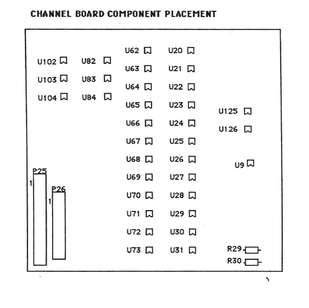
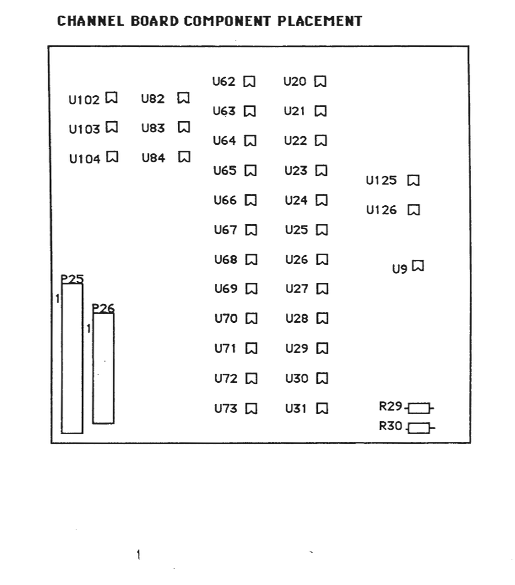
The following diagram of the Channel board shows the component placement of the integrated circuits which will be probed using an oscilloscope during the following Channel board test procedure. The point of view of this diagram is from the back of the instrument, looking down onto the Channel board.
CHANNEL BOARD COMPONENT PLACEMENT
Audio Mute Select
The audio output from the Channel board to the Audio board can be enabled or disabled by a relay which resides on the Channel board. After selecting the Channel test, the diagnostic will ask?
MUTE AUDIO OUTPUT?
If you press the YES switch the relay will be closed, disabling the audio output. If you press the NO switch the relay will be open, enabling the audio output.
Sinewave Select
One of three sinewaves stored in Sound File ROM may be selected. The sinewaves will be output to the selected channels continuously to provide oscilloscope signals. These sinewaves correspond to the keys on the keyboard and are therefore named accordingly. The sinewave names are:
C2 SINEWAVE sampled at 5 KHZ rate, frequency 65 HZ C5 SINEWAVE sampled at 10 KHZ rate, frequency 523 HZ C8 SINEWAVE sampled at 15 KHZ rate, frequency 4186 HZ
By selecting one of the three sinewaves, and selecting the same sampling rate as that used for originally storing the sinewaves, the frequency will be the same as that shown above. The diagnostic will ask:
C2 SINEWAVE? if you press the NO switch then it asks C5 SINEWAVE? if you press the NO switch then it asks C8 SINEWAVE? if you press the NO switch,
the questions are asked again. This will continue until you press the YES switch for one of the choices.
Sampling Rate Select
One of the four sampling rates may be selected. The sampling rate selected will apply to all channels activated during the channel select portion of the test. Therefore, each channel will have the same frequency sinewave output. The sampling rate choices are: 5kHz, 10kHz, 15kHz and 25kHz.
The frequency of the sinewave will vary depending upon the sampling rate selected. Table 1 shows the 12 possible frequencies available. The time (T) shown in Table 1 indicates the period of each sinewave. The diagnostic will ask:
5kHz SAMPLE RATE? If you press NO switch, then it asks
10kHz SAMPLE RATE? If you press NO switch, then it asks
15kHz SAMPLE RATE? If you press NO switch, then it asks
25kHz SAMPLE RATE? If you press NO switch, then it asks
these questions again until the YES switch is pressed.
Channel Select
Any combination of the twelve channels, numbered 1 through 12, may be selected for test. Each channel may have one of three attenuation settings and can be assigned to mixer Group A or Group B. As described in the Sampling Rate Select section, each channel will have the same frequency sinewave output. The diagnostic will ask:
TEST CHANNEL 1?
To test the channel, press the YES switch on the front panel. To disable the channel press the NO switch on the front panel. The diagnostic will ask this question for each of the channels 1 through 12. If you press the YES switch to select a channel for test, the diagnostic will ask the attenuation and group select questions described next.
Attenuation Select
One of the three channel amplitude control digital/analog converter settings may be selected for each channel. These settings are:
1. RAMP the amplitude DAC output 2. Maximum Attenuation 3. Minimum Attenuation
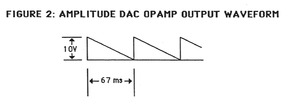
If RAMP the amplitude DAC output is chosen, the output signal of the amplitude DAC may be observed with an oscilloscope at the Channel board locations shown in Table 3. The output will appear as shown in figure 2. If maximum attenuation is selected the output of the amplitude DAC should be +10 VDC. If minimum attenuation is selected, the output of the amplitude DAC for that channel should be 0 VDC.
The diagnostic will ask:
RAMP AMP DAC? If you press the NO switch then it asks
MAXIMUM ATTENUATION? If you press the NO switch then
MINIMUM attenuation is used.
Group Select
Each of the 12 channels may be assigned to one of the two mixer outputs. These mixer outputs are designated Group A and Group B. The final audio outputs are designated LEFT and RIGHT. The channels assigned to Group A can be panned from left to right by moving the Group A slider on the front panel of the K250. Similarly, the channels assigned to Group B can be panned from left to right by moving the Group B slider on the front panel of the K250.
The diagnostic will ask:
ASSIGN TO GROUP A?
If you press the YES switch on the front panel, the channel will be assigned to mixer Group A. If you press the NO switch on the front panel, the channel is assigned to mixer Group B.
4.14 - CHANNEL AND AMPLITUDE DAC TEST
1. Select the CHANNEL TEST 2. Select AUDIO OUTPUT MUTED 3. Select C2 SINEWAVE at 5kHz SAMPLING RATE 4. Enable channels 1 through 12, ramp amplitude DACs, Group A 5. Use an oscilloscope and probe the test points indicated in Table 2 or 3 to verify channel operation. Probe the test points indicated in Table 4 to verify Amplitude DAC operation.
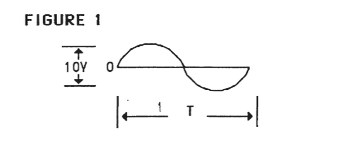
The frequency of the sinewave will vary depending upon the sampling rate selected. Table 1 shows the 12 possible frequencies available. The time (T) shown in Table 1 indicates the period of each sinewave. Figure 1 shows how the sinewave should appear at the outputs of the alias filters (See Table 2).
TABLE 1: SINEWAVE PERIOD TIMES (T)

SAMPLING RATE | C2 | C5 | C8
5kHz | 15 ms | 3.8 ms | 0.7 ms
10kHz | 7.5 ms | 1.9 ms | 35 ms
15kHz | 5.0 ms | 1.25 ms | 0.25 ms
25kHz | 3.0 ms | 0.75 ms | 0.15 ms
FIGURE 1
Sine wave diagram showing 1.0V amplitude and period T
The following table shows the integrated circuit pin numbers to probe with the oscilloscope to observe these sinewaves:
TABLE 2: ALIAS FILTER OUTPUTS
U20 | PIN 2 | CHANNEL 1
U21 | PIN 2 | CHANNEL 2
U22 | PIN 2 | CHANNEL 3
U23 | PIN 2 | CHANNEL 4
U24 | PIN 2 | CHANNEL 5
U25 | PIN 2 | CHANNEL 6
U26 | PIN 2 | CHANNEL 7
U27 | PIN 2 | CHANNEL 8
U28 | PIN 2 | CHANNEL 9
U29 | PIN 2 | CHANNEL 10
U30 | PIN 2 | CHANNEL 11
U31 | PIN 2 | CHANNEL 12
The following, Table 3, shows the Sample D/A Converter test points to probe if any of the Channel Alias Filter outputs are incorrect. The sinewaves at these points are not as clean in appearance.
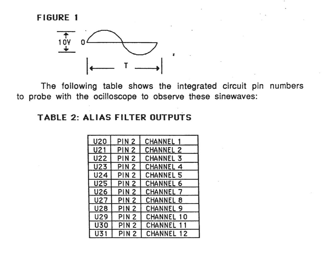
TABLE 3: SAMPLE DAC OUTPUTS
U62 PIN 20 CHANNEL 1
U63 PIN 20 CHANNEL 2
U64 PIN 20 CHANNEL 3
U65 PIN 20 CHANNEL 4
U66 PIN 20 CHANNEL 5
U67 PIN 20 CHANNEL 6
U68 PIN 20 CHANNEL 7
U69 PIN 20 CHANNEL 8
U70 PIN 20 CHANNEL 9
U71 PIN 20 CHANNEL 10
U72 PIN 20 CHANNEL 11
U73 PIN 20 CHANNEL 12
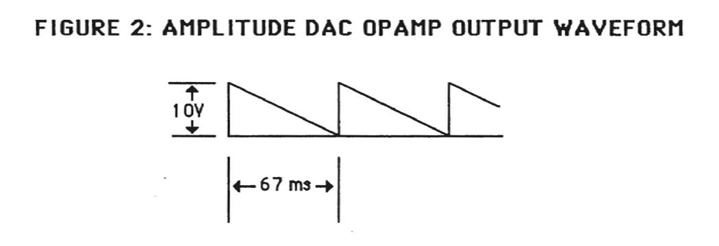
4.15 - AMPLITUDE DAC TEST
The Amplitude DAC output waveforms should appear as shown in figure 2 at each of the test points on the Channel board shown in Table 4.
FIGURE 2: AMPLITUDE DAC OPAMP OUTPUT WAVEFORM
TABLE 4: AMPLITUDE DAC OUTPUTS
U82 PIN 7 CHANNEL 1
U82 PIN 1 CHANNEL 2
U83 PIN 7 CHANNEL 3
U83 PIN 1 CHANNEL 4
U84 PIN 7 CHANNEL 5
U84 PIN 1 CHANNEL 6
U102 PIN 7 CHANNEL 7
U102 PIN 1 CHANNEL 8
U103 PIN 7 CHANNEL 9
U103 PIN 1 CHANNEL 10
U104 PIN 7 CHANNEL 11
U104 PIN 1 CHANNEL 12
4.16 - GROUP A/B MIXER AND LEFT/RIGHT AUDIO OUTPUT TEST
1. Select CHANNEL TEST
2. Select AUDIO OUTPUT NOT 'MUTED
3. Select C2 SINEWAVE, 5kHz SAMPLING RATE
4. Assign CHANNEL 1 with MINIMUM attenuation to GROUP A.
   Assign CHANNEL 2 with MINIMUM attenuation to GROUP B.
The GROUP A and GROUP B mixer outputs are available at the following test points:
U125, pin 1    GROUP A mixer output
U125, pin 7    FEEDBACK A output

U126, pin 1    GROUP B mixer output
U126, pin 7    FEEDBACK B output
- 5. Move the volume control slider on the K250 front panel to check the mixer gain control. The sinewave output should decrease in amplitude as the slider is moved left, and increase in amplitude as the slider is moved right.
The LEFT and RIGHT audio outputs are available at the following test points:
U9, pin 1 LEFT audio output U9, pin 1 RIGHT audio output R29 right end LEFT audio output R30 right end RIGHT audio output
- 6. While observing the sinewave at R29 right end, move the GROUP A and GROUP B sliders to the LEFT. The sinewave should decrease in amplitude. While observing the sinewave at R30 right end, move the GROUP A and GROUP B sliders to the RIGHT. The sinewave should decrease in amplitude.
- 7. Exit the Channel Test by pressing the SELECT switch.
4.17 - DIAGNOSTIC TEST PROCEDURE, REVISION D
Revision D Diagnostic EPROMs are for use with Kurzweil 250, Kurzweil 250X and Kurzweil RMX units with Version 3 or later software installed. If the instrument you are testing has less than Version 3 installed, you should test it with Revision B Diagnostics.
4.18 - INSTALLING DIAGNOSTIC EPROMS
1. Turn off system power
2. Open the slide chassis.
3. Remove U38 and U54 from the CPU board. Be careful when removing these EPROMs as you will be reinstalling them when the testing is complete.
4. Install U38 (Loc. 01) and U54 (Loc. 02) Diagnostic EPROMs in the empty sockets on the CPU board.
NOTE: When installing the diagnostic EPROMs, be sure pin 1 is facing the rear panel.
5. Turn on system power
NOTE: When the system is first turned on, the front panel LEDs may come on in an unpredictable pattern. They should all turn off after about one second.
6. The red power indicator light on the POD should be on. The front panel LCD should indicate:
K250 DIAGNOSTICS (C)
REV. D 11 JUL 86
The SELECT switch LED should be blinking on and off.
4.19 - POWER SUPPLY (POD) VOLTAGES
Before beginning the diagnostic test procedure, please be sure that the power supply voltages are correct. Verify the following:
1. The Power Supply (POD) provides:

   +5 volts DC
   +15 volts DC
   -15 volts DC
2. Using a VOM or DVM check the power supply voltages at the following power connectors:
4.20 - RUNNING THE DIAGNOSTIC TESTS
The Diagnostic tests check the following subsystems:
A. Front Panel assembly
B. CPU board
C. CGP board
D. Channel board
The SELECT switch and the YES and NO switches are used to select a test and answer the prompts displayed on the LCD. When a YES or NO response is required by the diagnostic test, the YES and NO switch LEDs will blink on and off alternately. When a SELECT response is required, the SELECT switch LED will be blinking in some instances, and no LEDs will be blinking in other instances. When no LEDs are blinking, only the SELECT switch has an effect when pressed.
4.21 - FRONT PANEL TESTS
The Front Panel tests check the following subassemblies:
1. LCD
2. Control Panel LEDs
3. Control Panel switches
4. Control Panel analog to digital converter:
External Pedal 1
Feedback from Channel board mixer, group B
Feedback from Channel board mixer, group A
Master Tune slider
Slider board voltage maximum
Slider board voltage minimum
External Pedal 2
Assignable Slider 3
Assignable Slider 2
Assignable Slider 1
Left Mod Lever
Right Mod Lever
Right POD Pedal
Left POD Pedal
4.22 - LCD TEST
To run the LCD test from the initial power up display message:
1. Press SELECT
2. Answer the displayed questions by pressing the YES or NO
   switch on the front panel as follows:

   CLR PWR FAIL CTN?  Press YES
   AUTOTEST?  Press NO
   RUN ALL TESTS?  Press NO
   FRONT PANEL?  Press YES
   ALL FP TESTS?  Press YES
The LCD should now display the following:
!"#$%&'()*+,-./ 0123 4567
89:;<=>?@ABCDEFGHIJKLMNO
Press SELECT
The LCD should now display the following:
PQRSTUVWXZ[]^ abcdefg

hijklmnopqrstuvwxyz{|}><!
4.23 - LED TEST
The LED test follows immediately after the LCD test by pressing SELECT. These four tests will step through in sequence automatically. To abort the LED tests, press and hold the SELECT switch.
The Front Panel LED test consists of four parts:
1. All LEDs on/off 10 times
2. One LED on at a time
3. One LED off at a time
4. Enable/disable LEDs on/off 10 times
4.24 - SWITCH TEST
After the LED test the LCD will indicate:
SWITCH TEST

PRESS ANY SWITCH
When any of the Front Panel switches is pressed, the switch number and function name will be displayed on the LCD. If the switch has an LED, the LED will blink on and off.
Press the SELECT switch to exit this test.
4.25 - ANALOG TO DIGITAL CONVERTER TEST
The ADC test will verify operation of some of the Front Panel Sliders as well as the Foot Pedals and Mod Levers. The LCD display will prompt for a YES or NO switch response as follows:
A/D CONVERTER TEST
EXT PED 1? Press YES
The LCD will show the A/D reading in HEX. for External Pedal 1 the approximate readings should be:
0 0     PEDAL NOT PLUGGED INTO REAR PANEL JACK

7E      PEDAL UP

0B      PEDAL DOWN
Press SELECT to proceed to the next ADC test.
FEEDBACK B? Press YES
The ADC reading should be approximately 7D.
Press SELECT to proceed to the next ADC test.
FEEDBACK A? Press YES
The ADC reading should be approximately 7F.
Press SELECT to proceed to the next ADC test.
MASTER TUNE? Press YES
The ADC reading should be approximately:
14      SLIDER IN LEFTMOST POSITION

8 1     SLIDER IN CENTER POSITION

ED      SLIDER IN RIGHTMOST POSITION
Press SELECT to proceed to the next ADC test.
- VOLTAGE MAX? Press YES
The ADC reading should be ED the same as the Master Tune rightmost position.
Press SELECT to proceed to next ADC test.
- VOLTAGE MIN? Press YES
The ADC reading should be 14 the same as the Master Tune leftmost position.
Press SELECT to proceed to the next ADC test.
- EXT PED 2? Press YES
The ADC readings should be approximately the same as for the External Pedal 1:
00       PEDAL NOT PLUGGED INTO REAR PANEL JACK

7E       PEDAL UP

0B       PEDAL DOWN
Press SELECT to proceed to the next ADC test.
- ASSN 3? Press YES
The ADC readings should be approximately the same as for the Master Tune slider:
14       SLIDER IN DOWN POSITION

80       SLIDER IN CENTER POSITION

ED       SLIDER IN UP POSITION
Press SELECT to proceed to the next ADC test.
- ASSN 2? Press YES
The ADC readings should be approximately the same as for the Master Tune slider:
14      SLIDER IN DOWN POSITION

80      SLIDER IN CENTER POSITION

ED      SLIDER IN UP POSITION
Press SELECT to proceed to the next ADC test.
LEFT MOD LEVER? Press YES
The Mod Lever ADC reading may vary since final calibration is performed during an audio test. The approximate readings should be:
80      MOD LEVER CENTERED

0A      MOD LEVER DOWN

EB      MOD LEVER UP
Press SELECT to proceed to the next ADC test.
RGT MOD LEVER? Press YES
The Mod Lever ADC reading may vary since final calibration is performed during an audio test. The approximate readings should be:
80      MOD LEVER CENTERED

0A      MOD LEVER DOWN

EB      MOD LEVER UP
Press SELECT to proceed to the next ADC test.
The POD foot pedals have three positions:
52      PEDAL UP

7B      PEDAL HALF WAY DOWN

A9      PEDAL DOWN
Press SELECT to proceed to the next ADC test.
LEFT PEDAL? Press YES
The left POD pedal readings should be approximately the same as the right pedal:
52         PEDAL UP

7B         PEDAL HALF WAY DOWN

A9         PEDAL DOWN
Press SELECT to exit the Front Panel Test and return to the main menu.
4.26 - CPU TESTS
Some of the CPU tests require the use of the loopback connectors provided in the Diagnostic Kit. These connectors are:
1. MIDI loopback connector
2. SYNC IN/OUT loopback connector (also used for CLICK OUT /TRIG IN)
3. Parallel Computer (PC) loopback connector
Starting with the first main menu question displayed on the Front Panel LCD, press the YES, NO or SELECT switch in response to the display prompts as follows:
CLR PWR FAIL CNT? Press YES

AUTOTEST? Press NO

RUN ALL TESTS? Press NO

FRONT PANEL? Press NO

TEST CPU? Press YES

ALL CPU TESTS? Press NO

TEST CPU RAM? Press YES

ALL CPU RAM? Press YES
The diagnostic will now proceed to test the main CPU random access memory (RAM). If there is an error during the test, a diagnostic error message will be displayed on the front panel LCD indicating the address of the error, the expected (good) data, and the actual (bad) data read.
EXAMPLE:
RAM TEST ERR A: 1003FF <<<< THIS IS THE ADDRESS
GOOD: 55    BAD: FF
If the RAM data error occurs, the individual RAM tests may be run to determine the memory chip component number. After each memory test questions, a LOOP ON TEST? question is asked. If YES is the response, the test will repeat until SELECT is pressed or an error is detected.
If there are no main RAM errors, the next LCD prompt will be:
TEST OPTIONAL RAM?
(NOTE: This RAM is standard on newer units and should be installed in units with Version 3 or better.)
The response to this question is NO if the sequencer RAM is not installed on the CPU board. The response is YES, if the RAM is present. If the test passes the next prompt will be:
TEST INDIVIDUAL RAM?
The response to this question is NO if the previous RAM test(s) have run successfully with no error messages displayed. The response to the this question is YES, if there were errors during the previous RAM test(s). If you respond with YES, the following prompts will be displayed:
MAIN CPU RAM
TEST U33?
TEST U49?
TEST U32?
TEST U48?
TEST U31?
TEST U47?
TEST U30?
TEST U46?
TEST U29?
TEST U44?
TEST U28?
TEST U43?
OPTIONAL CPU RAM
TEST U26?
TEST U41?
TEST U25?
TEST U40?
The next prompt after the RAM tests is:
TEST CPU ROM? Press YES
ALL CPU ROM? Press YES
The CHECKSUM for each EPROM will be displayed on the LCD. The CHECKSUMs are for the following EPROMs:
U38		(DIAGNOSTIC EPROM)
U54		(DIAGNOSTIC EPROM)
U37
U53
U36
U52
U35
U51
U26
U41
U25
U40
The 8254 timers are the next CPU components checked. The outputs of the timers are Pins 10, 13 and 17. The prompt is:
INIT TIMERS? Press YES
Using an oscilloscope with probe, check for the following square waves at the IC and pin number indicated:
IC NUMBER PIN NUMBER SQUARE WAVE PERIOD U68 10 200 nsec. U68 13 400 nsec. U68 17 600 nsec. U69 10 800 nsec. U69 13 1 μsec. U69 17 2 μsec.IC NUMBER PIN NUMBER SQUARE WAVE PERIOD U87 10 3 μsec. U87 13 4 μsec. U87 17 5 μsec. U88 10 6 μsec. U88 13 7 μsec. U88 17 8 μsec. U106 10 9 μsec. U106 13 25 μsec. U106 17 50 μsec. U107 10 75 μsec. U107 13 100 μsec. U107 17 125 μsec. U118 10 150 μsec. U118 13 175 μsec. U118 17 200 μsec. U119 10 225 μsec. U119 13 250 μsec. U119 17 500 μsec.
The next CPU test is the keyboard interface test.
TEST KEYBOARD? Press YES
KEYBOARD TEST PRESS ANY KEY
The first key on the left is numbered zero. The last key on the right is numbered 87. The keyboard is divided into two keyswitch boards. The left half of the keyboard contains keys 0 through 43. The right half of the keyboard contains keys 44 through 87. The keyboard split occurs between E4 and F4 in the center of the keyboard.
Pressing and holding down the E4 key on the keyboard will NOT sound an audible note, but will cause the front panel LCD to show:
EXAMPLE:


ATTACK KEY 43

TOF: F0     COUNT: 1
Releasing the E4 key will cause the front panel display to show:
RELEASE KEY: 43
TOF: 93      COUNT: 2
Press SELECT to exit the keyboard test.
The next four tests require the loopback connectors provided with the Diagnostic Kit.
TEST MIDI? Press YES
- Disconnect the MIDI connector from the CPU board and plug in the MIDI loopback connector.
- Press SELECT to begin the test.
If a test error occurs a diagnostic error message will be displayed on the front panel LCD. If no error occurs, proceed with the following.
IF YOUR UNIT HAS QLS DO NOT USE
- TEST PC? Press YES
- Connect the Parallel loopback connector to the computer port located on the back panel.
- Press SELECT to being the test.
If a test error occurs a diagnostic error message will be displayed on the front panel LCD. If no error occurs, proceed with the following.
- TEST SYNC LO? YES
- Connect the 1/4" to 1/4" cable supplied with the Diagnostic Kit. Connect this cable from SYNC OUT to SYNC IN.
TEST U67 TIMER 1? Press YES
If a test error occurs a diagnostic error message will be displayed on the front panel LCD display. If no error occurs, proceed with the following.
Press SELECT to exit the CPU tests.
4.27 - POWER FAIL TEST
To check the power fail interrupt logic on the CPU board:
CLR PWR FAIL CNT? Press YES
Turn off system power, then turn on system power.
Press SELECT
CLR PWR FAIL CNT? Press NO
COUNT: 1
The COUNT indicates the number of times a power fail interrupt was detected by the CPU. Cycling the power off then on several more times and answering NO to the CLR PWR FAIL CNT prompt should increment the count by one each time. If the count does not increment by one, there may be a problem with the CPU interrupt logic or the battery-backed RAM.
4.28 - CGP TESTS
CGP RAM
Starting with the first main menu question displayed on the front panel display, press the YES, NO or SELECT switch in response to the display prompts as follows:
- CLR PWR FAIL CNT? Press YES
AUTOTEST? Press NO
RUN ALL TESTS? Press NO
FRONT PANEL? Press NO
TEST CPU? Press NO
TEST CGP? Press YES
ALL CGP TESTS? Press NO
TEST CGP RAM? Press YES
LOOP ON TEST? YES or NO
The diagnostic will now proceed to test the CGP random access memory (RAM). If there is an error during the test, a diagnostic error message will be displayed on the front panel LCD display indicating the address of the error, the expected (good) data, and the actual (bad) data read.
EXAMPLE:
RAM TEST ERR A: 1B03FE <<<< This is the address

GOOD: 5555                BAD: FFFF
Press SELECT to proceed. If LOOP ON TEST is selected, the test will repeat until an error is detected or SELECT is pressed and held until the test is complete.
SOUND FILE RAM
- TEST SF RAM WORD? Press YES or NO
LOOP ON TEST? Press YES or NO
The response to this questions is NO if the digitizer optional RAM is not present on the CGP board, or if SUPERAM is installed.
The response is YES if the digitizer RAM is present on the CGP. If an error occurs, the error message will appear as in the example for the CGP RAM.
If LOOP ON TEST is selected, the test will repeat until an error is detected or SELECT is pressed and held until the end of the test.
TEST SF RAM SOUND? Press YES or NO

LOOP ON TEST? Press YES or NO
The response to this questions is NO if the digitizer optional RAM is not present on the CGP board, or if SUPERAM is installed.
The response is YES if the digitizer RAM is present on the CGP. If an error occurs, the error message will appear as in the example for the CGP RAM. If LOOP ON TEST is selected, the test will repeat until an error is detected or SELECT is pressed and held until the test is complete. This could take as long as 30 seconds for this test.
SOUND FILE ROM
There are two configurations of Sound File ROM. The early configuration consists of six rows of ten 256K ROMs per row. In that configuration, optional sound blocks are installed on a daughter board. The diagnostic program expects to find only Sound Block A and B on the daughter board. The current configuration consists of two rows of ten 1M ROMs each. In this configuration, optional sound blocks are installed in the extra rows on the CGP board. The rows are numbered from 1 to 6 starting from the row nearest to the rear of the instrument. Rows 1 and 2 contain the basic sounds that all units produced with this 1M, board configuration are produced with. Row 3 is reserved for the optional Sound Block A. Row 4 is reserved for the optional Sound Block B. Row 5 is reserved for the optional Sound Block C. Row 6 is reserved for the optional Sound Block D. There are four checksums per row in the current configuration.
If a checksum error occurs during the test, the ROM component number on the CGP will be displayed along with the expected checksum (GOOD) and the actual checksum (BAD):
EXAMPLE:
CGP ROM CHKSUM ERR U125
GOOD: 354B         BAD: 7894
TEST SF ROM? Press YES

LOOP ON TEST? Press YES or NO
As the sound file ROM test proceeds, the LCD display will show:
TESTING SF ROM ROW 1

TESTING SF ROM ROW 2
If the early configuration is being tested, the following will also be displayed:
TESTING SF ROM ROW 3
TESTING SF ROM ROW 4
TESTING SF ROM ROW 5
TESTING SF ROM ROW 6
If LOOP ON TEST is selected, the message:
LOOPING ON TEST
will be displayed on the second line of the display, and the test will repeat until an error is detected or SELECT is pressed and held until Row 6 (early configuration) or row 2 (current configuration) has been tested.
OPTIONAL SOUND FILE ROM
Optional sounds are Sound Blocks A, B, C and D. In the early configuration Sound Blocks A and B are installed on a daughter board. The daughter board sound file ROM is divided logically into eight rows of ten ROMs each. Physically, there are actually only two rows of ten 1M ROMs each. In the later configuration optional sound blocks are installed in rows 3 through 6 on the CGP board.
If a checksum error occurs during the test, the ROM component number on the CGP or daughter board will be displayed along with the expected checksum (GOOD) and the actual checksum (BAD):
EXAMPLE:
CGP ROM CHKSUM ERR U26
GOOD: 9FEA          BAD: 7894
TEST SOUND BLOCK A?
YES (to test Block A)
NO (to go to next test)
LOOP ON TEST? Press YES or NO
As the sound file ROM test proceeds, the LCD will show:
TESTING SOUND BLOCK A
LOOPING ON TEST (if selected)
If LOOP ON TEST is selected, the test will repeat until an error is detected or SELECT is pressed and held until the last chip has been tested. After exiting from the Sound Block A test, or after responding NO to the Sound Block A test, the display will show:
TEST SOUND BLOCK B?
YES (to test Block B)
NO (to go to next test)
LOOP ON TEST? Press YES or NO
As the sound file ROM test proceeds, the LCD will show:
TESTING SOUND BLOCK B
LOOPING ON TEST (if selected)
If LOOP ON TEST is selected, the test will repeat until an error is detected or SELECT is pressed and held until the last chip has been tested. After exiting from the Sound Block B test, or after responding NO to the Sound Block B test, the display will show:
TEST SOUND BLOCK C?
YES (to test Block C)
NO (to go to next test)
LOOP ON TEST? Press YES or NO
As the sound file ROM test proceeds, the LCD will show:
TESTING SOUND BLOCK C

LOOPING ON TEST (if selected)
If LOOP ON TEST is selected, the test will repeat until an error is detected or SELECT is pressed and held until the last chip has been tested. After exiting from the Sound Block C test, or after responding NO to the Sound Block C test, the display will show:
TEST SOUND BLOCK D?

YES (to test Block D)

NO (to go to next test)


LOOP ON TEST? Press YES or NO
As the sound file ROM test proceeds, the LCD will show:
TESTING SOUND BLOCK D

LOOPING ON TEST (if selected)
If LOOP ON TEST is selected, the test will repeat until an error is detected or SELECT is pressed and held until the last chip has been tested.
The daughter board Sound Block A ROM component numbers are:
U26, U2, U5, U8, U11, U28, U14, U17, U20 and U23
The daughter board Sound Block B ROM component numbers are:
U1, U4, U7, U10, U13, U16, U19, U22, U25 and U27.
EXTERNAL CARTRIDGE SOUND FILE ROM (K250 only)
This test should not be used. The external cartridge has diagnostics in the K250 software.
CGP STATUS TEST
TEST CGP DMA? Press YES
CHANNEL 1? Press YES or NO
Each successive channel number will be asked until a YES response is given. Only one channel may be tested at a time.
During the CGP status test, the test status will be displayed on the front panel LCD as follows:
EXAMPLE:
CSW:D00F

AL1: E7F1    AL2:0000
In the above example, the CSW is the channel status word. The four status digits are in hexadecimal. If the test is progressing correctly:
1. The first CSW digit will usually vary from D to F. Occasionally, it will flash briefly from D to 5 or from F to 7. If 5 or 7 are displayed for any appreciable length of time, there may be a problem on the CGP board. Any number or letter other than D, F, 5 or 7 in the first character of the CSW also indicates a problem on the CGP board.
2. The second and third digits will increment in pairs from 00 to FF.
3. The fourth CSW digit should always be F.
4. AL1 will count up from 0000 to FFFF and then stop. When AL1 reaches FFFF, AL2 will start counting up from 0000 to FFFF and then stop. AL1 will then begin counting up again from 0000 to FFFF. AL1 and AL2 will continue counting up alternately until SELECT is pressed.
CSW: 900F
AL1: 0010       AL2: 0000
If this error occurs, check the ribbon cable connections going from the CPU board to the channel board. Also run the CPU timer test.
Press SELECT to exit the CCP test.
4.29 - DIGITIZER TEST
The digitizer test requires a 1/4" monaural audio cable, similar to the one used for the SYNC IN/OUT loopback. An oscilloscope with probe grounded to the instrument chassis ground, and a pair of stereo headphones are the only other equipment required in addition to the K250.
SETUP PROCEDURE
1. Connect one end of the 1/4" monaural audio cable to the LEFT HI audio output jack on the rear panel of the K250. Connect the other end of the audio cable to the LINE IN jack on the rear panel of the K250. 2. Set the GROUP A slider to the leftmost position. 3. Set the GROUP B slider to the rightmost position. 4. Set the VOLUME slider to the rightmost position (maximum).
TEST DESCRIPTION
The digitizer test will use the K250 channel 1 as the signal source to be digitized. Channel 12 will be set up in digitizer mode and will be used to sample the input signal coming in from the LINE IN jack. When the sampling is complete, the original channel 1 sinewave signal will be output on channel 1, Group A. The digitized sinewave signal will be output on channel 2, Group B for comparison. The channel 2 signal will be lower in amplitude than the channel 1 signal, but should not have distortion or noise present. The audio output has been enabled during the test to permit aural verification. The channel 1 signal should be audible on the left headphone speaker, and the channel 2 digitized signal should be audible on the right headphone speaker, at a slightly lower volume.
SELECTING THE DIGITIZER TEST
Starting with the first main menu question displayed on the front panel display, press the YES, NO or SELECT switch in response to the display prompts as follows:
- CLR PWR FAIL CNT? Press YES
AUTOTEST? Press NO
RUN ALL TESTS? Press NO
FRONT PANEL? Press NO
TEST CPU? Press NO
TEST CGP? Press NO
TEST CHANNELS? Press YES
TEST DIGITIZER? Press YES
There is a choice of one of three sinewaves to sample:
- C8 SINEWAVE? Press YES or NO
C5 SINEWAVE? Press YES or NO
C2 SINEWAVE? Press YES or NO
After selecting one of the sinewaves, the display will show:
TEST DIGITIZER
After a one second sampling period, the display will show:
TEST DIGITIZER

SCOPE CHANNEL 1 AND 2
At this point, the digitized output signal should be available:
CHANNEL SIGNAL FREQUENCY PERIOD AMPLITUDE
1 C2 SINEWAVE 65HZ 15.29 MS 10V P-P
1 C5 SINEWAVE 523HZ 1.91 MS 10V P-P
1 C8 SINEWAVE 4186HZ 239US 8.8V P-P
Location U20, Pin 2 on the Channel board
CHANNEL SIGNAL FREQUENCY PERIOD AMPLITUDE
1 C2 SINEWAVE 65HZ 15.29 msec. 6.2VP-P
1 C5 SINEWAVE 529HZ 1.91 msec. 6.4VP-P
1 C8 SINEWAVE 4186HZ 239 usec. 6VP-P
Location U21, Pin 2 on the Channel board.
During the approximately 1 second of input sampling, the input signal can be checked with the scope at U60, Pin 13. This is the A/D converter input pin.
The diagnostic chips are not capable of testing the digitizer at rates higher than 15KHz. If the unit passes all diagnostic tests, the digitizer may be tested at rates above 15KHz. using the following procedure:
4.30 - 50KHz. SAMPLING OPTION DIAGNOSTIC TEST
EQUIPMENT REQUIRED:
1. Sine Wave Generator, capable of generating 8KHz. with an amplitude of 0.5 VPP.
2. Dual trace oscilloscope
3. Cable to connect sine wave generator to LINE IN jack on the K250
4. Piezoelectric microphone or equivalent (only used for checking MIC input circuit)
5. 1/4" plug to bare wires (to observe the output of the K250 on the scope)
6. Version 3 or later software with same version sampling software.
Set-Up:
The diagnostic EPROMs should be removed and the system operating software should be reinstalled. Check to be sure that the software has been installed correctly. Connect the sine wave generator to the K250 LINE IN jack. Connect one trace of the scope to the output of the sine wave generator and the other trace to the left or right HI output on the K250. Set Group A and B sliders to center. Adjust the frequency of the sine wave generator to aproximately 8KHz. and the amplitude to approximately 0.5 VPP.
Procedure
LCD READS			PRESS		COMMENTS

KURZWEIL GRAND PIANO		INSTRUMENT	Display on power up
PLAY MODE

RECORD SOUND?			SELECT		Active sampling
DIG 1

Sound type (1-6):			SELECT		Using QUICKTAKE
QUICKTAKE 1						achieves the fastest
								turnaround time
Sampling rate (1-14):
25000 10
14, SELECT
Select the highest sampling rate. If the unit has not been upgraded to 50K, 25K will be the highest rate.
Sampling rate (1-14):
5000 14
SELECT
(or 25000 10)
Time to record:
SELECT
Use maximum 10 sampling time (20 at 25000)
Trigger level (0-6): 24dB 3
SELECT
Pre-trigger recording? NONE0
SELECT
Check level?
YES
CONTINUOUS**** PEAK HOLD* *
VU meter display
Set volume slider to full. Use slider 3 to set gain. The right end of both CONTINUOUS and PEAK HOLD will change to "+" signs and 'SPLIT KBD" button will light if you are clipping. If you can't reach clipping with slider 3 all the way up, slowly increase the output on the sine wave generator until clipping is indicated. Now back off slider 3 to a level as close as possible to clipping without actually clipping. You are now ready to sample:
CONTINUOUS********** PEAK HOLD* *
SELECT
Done setting level
HIT RECORD TO START
RECORD
Record sound
RECORDING...
DONE. EVALUATING...
CLIPS 0 MAX XXX
Preview root at C4
- Hit SELECT to continue
While playing C4 (middle C), observe the output of the K250 on the scope. Look for distortion, glitches and discontinuities in the waveform. Compare the output of the K250 with the output of the sine wave generator. The two should be identical in frequency. The amplitude of the output from the K250 will depend on how hard you hit the key.
SELECT
Save this sound? (Y/N) NO
Retake? (Y/N) NO
RECORD SOUND? PLAY
DIG 1
KURZWEIL GRAND PIANO
PLAY MODE
Disconnect the scope and the sine wave generator. Connect the microphone to the MIC jack on the K250. Repeat the procedure outlined above. Make some sound when the display says RECORDING... Using pure tonal sounds will make it easier to detect and diagnose any possible problems. It is not necessary to observe the output on the scope this time unless problems are encountered.
4.31 - CHANNEL BOARD TESTS
The following diagram of the Channel board shows the component placement of the integrated circuits which will be probed using an oscilloscope during the following Channel board test procedure. The point of view of this diagram is from the back of the instrument, looking down onto the Channel board.
Audio Mute Select
The audio output from the Channel board to the Audio board can be enabled or disabled by a relay which resides on the Channel board. After selecting the Channel test, the diagnostic will ask?
MUTE AUDIO OUTPUT?
If you press the YES switch the relay will be closed, disabling the audio output. If you press the NO switch the relay will be open, enabling the audio output.
Sinewave Select
One of three sinewaves stored in Sound File ROM may be selected. The sinewaves will be output to the selected channels continuously to provide oscilloscope signals. These sinewaves correspond to the keys on the keyboard and are therefore named accordingly. The sinewave names are:
C2 SINEWAVE sampled at 5 KHZ rate, frequency 65 HZ
C5 SINEWAVE sampled at 10 KHZ rate, frequency 523 HZ
C8 SINEWAVE sampled at 15 KHZ rate, frequency 4186 HZ
By selecting one of the three sinewaves, and selecting the same sampling rate as that used for originally storing the sinewaves, the frequency will be the same as that shown above. The diagnostic will ask:
Sampling Rate Select
One of the four sampling rates may be selected. The sampling rate selected will apply to all channels activated during the channel select portion of the test. Therefore, each channel will have the same frequency sinewave output. The sampling rate choices are: 5kHz, 10kHz, 15kHz and 25kHz.
The frequency of the sinewave will vary depending upon the sampling rate selected. Table 1 shows the 12 possible frequencies available. The time (T) shown in Table 1 indicates the period of each sinewave. The diagnostic will ask:
5kHz SAMPLE RATE? If you press NO switch, then it asks

10kHz SAMPLE RATE? If you press NO switch, then it asks

15kHz SAMPLE RATE? If you press NO switch, then it asks

25kHz SAMPLE RATE? If you press NO switch, then it asks
these questions again until the YES switch is pressed.
Channel Select
Any combination of the twelve channels, numbered 1 through 12, may be selected for test. Each channel may have one of three attenuation settings and can be assigned to mixer Group A or Group B. As described in the Sampling Rate Select section, each channel will have the same frequency sinewave output. The diagnostic will ask:
TEST CHANNEL 1?
To test the channel, press the YES switch on the front panel. To disable the channel press the NO switch on the front panel. The diagnostic will ask this question for each of the channels 1 through 12. If you press the YES switch to select a channel for test, the diagnostic will ask the attenuation and group select questions described next.
Attenuation Select
One of the three channel amplitude control digital/analog converter settings may be selected for each channel. These settings are:
1. RAMP the amplitude DAC output
2. Maximum Attenuation
3. Assign to Group A
If RAMP the amplitude DAC output is chosen, the ouput signal of the amplitude DAC may be observed with an oscilloscope at the Channel board locations shown in Table 3. If maximum attenuation is selected the output of the amplitude DAC should be +10 VDC. If minimum attenuation is selected, the output of the amplitude DAC for that channel should be 0 VDC.
The diagnostic will ask:
RAMP AMP DAC? If you press the NO switch then it asks MAXIMUM ATTENUATION? If you press the NO switch then MINIMUM attenuation is used.
Group Select
Each of the 12 channels may be assigned to one of the two mixer outputs. These mixer outputs are designated LEFT and RIGHT. The channels assigned to Group A can be panned from left to right by moving the Group A slider on the front panel of the K250. Similarly, the channels assigned to Group B can be panned from left to right by moving the Group B slider on the front panel of the K250.
The diagnostic will ask:
ASSIGN TO GROUP A?
If you press the YES switch on the front panel, the channel will be assigned to mixer Group A. If you press the NO switch on the front panel, the channel is assigned to mixer Group B.
ALL CHANNELS TEST
To select the ALL CHANNELS test, answer:
TEST CHANNELS? Press YES' MUTE AUDIO OUTPUT? Press YES or NO
If you press the YES switch, the relay will be closed disabling the audio output. If you press the NO switch, the relay will be open, enabling the audio output.
All 12 channels will be enabled, with a different frequency sinewave on each channel. Channel 1 will have the lowest frequency sinewave, and channel 12 will have the highest frequency sinewave. The signals can be checked on pin 2 of each of the alias filter outputs shown in table 2. The following table shows the frequencies expected for each channel:
CHANNEL	SIGNAL		SAMPLE RATE	FREQ.	PERIOD

1	C2 SINEWAVE	5KHZ		65HZ	15.3 msec.
2	C2 SINEWAVE	10KHZ		130HZ	7.6 msec.
3	C2 SINEWAVE	15KHZ		195HZ	5.1 msec.
4	C2 SINEWAVE	25KHZ		325HZ	3.1 msec.
5	C5 SINEWAVE	5KHZ		261HZ	3.8 msec.
6	C5 SINEWAVE	10KHZ		523HZ	1.9 msec.
7	C5 SINEWAVE	15KHZ		783HZ	1.3 msec.
8	C5 SINEWAVE	25KHZ		1305HZ	766 μsec.
9	C8 SINEWAVE	5KHZ		1395HZ	716 μsec.
10	C8 SINEWAVE	10KHZ		2790HZ	358 μsec.
11	C8 SINEWAVE	15KHZ		4186HZ	239 μsec.
12	C8 SINEWAVE	25KHZ		6976HZ	143 μsec.
4.32 - CHANNEL AND AMPLITUDE DAC TEST
1. Select the CHANNEL TEST by pressing the YES switch when the TEST ANY CHANNEL? is displayed.
2. Select audio output muted
3. Select C2 sinewave at 5kHz sampling rate
4. Enable channels 1 through 12, ramp amplitude DACs, Group A
5. Use an oscilloscope and probe the test points indicated in Table 2 or 3 to verify channel operation. Probe the test points indicated in Table 4 ot verify Amplitude DAC operation.
The frequency of the sinewave will vary depending upon the sampling rate selected. Table 1 shows the 12 possible frequencies available. The time (T) shown in Table 1 indicates the period of each sinewave. Figure 1 shows how the sinewave should appear at the outputs of the alias filters (See Table 2).
TABLE 1: SINEWAVE PERIOD TIMES (T)
SAMPLING RATE | C2 | C5 | C8
5kHz | 15 ms | 3.8 ms | 0.7 ms
10kHz | 7.5 ms | 1.9 ms | .35 ms
15kHz | 5.0 ms | 1.25 ms | 0.25 ms
25kHz | 3.0 ms | 0.75 ms | 0.15 ms
The following table shows the integrated circuit pin numbers to probe with the oscilloscope to observe these sinewaves:
TABLE 2: ALIAS FILTER OUTPUTS
U20  PIN 2  CHANNEL 1
U21  PIN 2  CHANNEL 2
U22  PIN 2  CHANNEL 3
U23  PIN 2  CHANNEL 4
U24  PIN 2  CHANNEL 5
U25  PIN 2  CHANNEL 6
U26  PIN 2  CHANNEL 7
U27  PIN 2  CHANNEL 8
U28  PIN 2  CHANNEL 9
U29  PIN 2  CHANNEL 10
U30  PIN 2  CHANNEL 11
U31  PIN 2  CHANNEL 12
The following, Table 3, shows the Sample D/A Converter test points to probe if any of the Channel Alias Filter outputs are incorrect. The sinewaves at these points are not as clean in appearance.
TABLE 3: SAMPLE DAC OUTPUTS
U62  PIN 20  CHANNEL 1
U63  PIN 20  CHANNEL 2
U64  PIN 20  CHANNEL 3
U65  PIN 20  CHANNEL 4
U66  PIN 20  CHANNEL 5
U67  PIN 20  CHANNEL 6
U68  PIN 20  CHANNEL 7
U69  PIN 20  CHANNEL 8
U70  PIN 20  CHANNEL 9
U71  PIN 20  CHANNEL 10
U72  PIN 20  CHANNEL 11
U73  PIN 20  CHANNEL 12
4.33 - AMPLITUDE DAC TEST
The Amplitude DAC output waveforms should appear as shown in figure 2 at each of the test points on the Channel board shown in Table 4.
FIGURE 2: AMPLITUDE DAC OPAMP OUTPUT WAVEFORM
TABLE 4: AMPLITUDE DAC OUTPUTS

U82  PIN 7  CHANNEL 1
U82  PIN 1  CHANNEL 2
U83  PIN 7  CHANNEL 3
U83  PIN 1  CHANNEL 4
U84  PIN 7  CHANNEL 5
U84  PIN 1  CHANNEL 6
U102 PIN 7  CHANNEL 7
U102 PIN 1  CHANNEL 8
U103 PIN 7  CHANNEL 9
U103 PIN 1  CHANNEL 10
U104 PIN 7  CHANNEL 11
U104 PIN 1  CHANNEL 12
4.34 - GROUP A/B MIXER AND LEFT/RIGHT AUDIO OUTPUT TEST
1. Select CHANNEL TEST
2. Select AUDIO OUTPUT NOT MUTED
3. Select C2 SINEWAVE, 5kHz SAMPLING RATE
4. Assign CHANNEL 1 with MINIMUM attenuation to GROUP A.
   Assign CHANNEL 2 with MINIMUM attenuation to GROUP B.
The GROUP A and GROUP B mixer outputs are available at the following test points:
U125, pin 1      GROUP A mixer output
U125, pin 7      FEEDBACK A output

U126, pin 1      GROUP B mixer output
U126, pin 7      FEEDBACK B output
- 5. Move the volume control slider on the K250 front panel to check the mixer gain control. The sinewave output should decrease in amplitude as the slider is moved left, and increase in amplitude as the slider is moved right.
The LEFT and RIGHT audio outputs are available at the following test points:
U9, pin 1                    LEFT audio output
U9, pin 1                    RIGHT audio output

R29 right end               LEFT audio output
R30 right end               RIGHT audio output
- 6. While observing the sinewave at R29 right end, move the GROUP A and GROUP B sliders to the LEFT. The sinewave should decrease in amplitude. While observing the sinewave at R30 right end, move the GROUP A and GROUP B sliders to the RIGHT. The sinewave should decrease in amplitude.
- 7. Exit the Channel Test by pressing the SELECT switch.