Chapter 5 - Disassembly/Assembly Procedures
5.1 - KURZWEIL 250
5.1.1 - Kurzweil 250 Enclosure
The Kurzweil 250 cabinet enclosure is two halves, a top and a bottom half. Should a repair require the top enclosure to be removed, you will need to loosen 7 captive screws that secure the top enclosure. The 7 captive screws are located under the unit. They come up through the bottom enclosure securing the top half. Loosen the screws until they move freely.
Once the 7 captive screws are loose, carefully lift the top enclosure up. You should be standing at the keyboard when you begin to lift the top enclosure. Next disconnect the following: a flat ribbon cable coming from the Channel board to the Slider board, a flat ribbon cable coming from the CPU board to the Control Panel board and a ground strap that is connected to the right hand side of the faceplate. You can now completely lift off the top enclosure.
5.1.2 - Kurzweil 250 Slide Chassis
The Kurzweil 250 Slide Chassis is secured by 3 phillips head screws. They come up through the bottom enclosure securing the slide chassis. The 3 screws are spaced proportionally along the rear panel. To open the slide chassis, simply remove the screws. You will notice 2 handles mounted on the rear panel. Once the 3 screws have been removed, pull on these handles to release the slide chassis. The slide chassis will pull out about 14 inches. Please note that the slide chassis when completely open does not clear the large printed circuit boards mounted to the slide chassis.
Once you have opened the slide chassis, the following boards will be visible to you: CPU, CGP, Channel and Audio.
5.1.3 - CPU Board
To remove the CPU board, it is necessary to disconnect all cables connected to the CPU. There are 4 flat ribbon cables to be removed: 1 from the CGP board (center board), one from the Channel board (right-hand side) and two ribbon cables that connect to the inside edge of the CPU (these two cables come from the Control Panel and Keyswitch boards). Next, remove the two brown power connectors and the MIDI cable located next to the rear panel on the CPU. Now it is necessary to remove the 4 fastening nuts securing the four 1/4 inch phone jacks to the rear panel. Then remove the 13 phillips head screws which mount the CPU to the slide chassis. It is necessary to have a very short screwdriver to remove the 2 screws located at the inner edge of the board.
5.1.4 - CGP Board
To remove the CGP board, it will be necessary to remove 6 cables. Two from the CGP board to the Channel board, two from the CGP board to the CPU board, one from the power connector to the CGP board and one long flat ribbon cable that goes across the CGP board from the CPU to the Channel board. Once the cables have been disconnected, remove the 13 phillips head screws holding the CGP to the chassis. It is necessary to have a very short screwdriver to remove the 2 screws located at the inner edge of the board.
5.1.5 - Channel Board
To remove the Channel board, it will be necessary to remove the following cables: 1 from the Audio board to the Channel board, 1 from the power connector to the Channel board, 1 coming from the Slider board to the Channel board, 1 coming from the CPU to the Channel board and 1 coming from the CGP to the Channel board. It is not always necessary to remove the shield. However, if you are replacing the Channel board, be sure that the shield is put on the replacement. Once the cables have been disconnected, remove the 13 phillips head screws holding the Channel board to the chassis. It is necessary to have a very short screwdriver to remove the 2 screws located at the inner edge of the board.
5.1.6 - Audio Board
To remove the Audio board, simply disconnect the ribbon cable from the Audio board to the Channel board. Next, remove all hardware securing it to the rear panel.
Kurzweil 250 Service Manual, Chapter 5 5 - 4
5.2 - FRONT PANEL ASSEMBLY
5.2.1 - Accessing the Front Panel Assembly
With this procedure you can reach and remove the three boards mounted on the Front Panel assembly. You can also remove all but two of the wooden keys with the Front Panel up. For most repairs, you will not have to remove the entire Front Panel assembly from the instrument.
There are three steps for opening up the Front Panel assembly:
1. Loosen the two captive screws on the Front Panel assembly. (One screw at each end of the Front Panel assembly.) 2. Lift the Front Panel assembly from its bottom edge (edge that meets keyboard). Carefully lift the assembly up and towards you about an inch. At this point the assembly could rest on the sharp and flat keys. 3. The assembly is now free and can be pivoted up and back so that the faceplate rests up against the top enclosure (see illustration below).
With the Front Panel assembly in this position, you can reach the three boards.
Figure 5.1

5.2.2 - Removing the Front Panel Assembly
Should you have to remove the entire Front Panel assembly, lift the assembly into its service position and disconnect the Mod Lever cable, the Slider board cable, the Control Panel cable and the ground strap wire. The ground strap wire will require a 5/16 nut driver.
Pivot the front edge of the assembly down towards the bottom enclosure and carefully bend the flange of either the left or right pivot bracket towards the center of the keyboard. Then lift that end of the assembly free of the pin. The entire assembly can now be removed.
5.2.3 - Closing the Front Panel Assembly
To return the Front Panel assembly to its operating position, grasp either end of the panel and pivot it down until it is flat (parallel to the ground). Now lift the panel up, keeping it level, until the pivot points are at the bottom of the grooves. Then push the panel towards the back of the instrument about one inch, lifting the back of the assembly so that the top edge of the assembly is above the supporting flange on the top enclosure, and the three clips attached underneath the the assembly go under the flange.
As you push the panel back into place, make sure all the cables are inside the cabinet. The cables must lie above the damper bar so they do not rest on the keys.
Now gently push the front edge of the assembly down behind the keys and tighten the 2 captive screws. Do not over-torque the mounting screws.
5.3 - KEYBOARD ASSEMBLY
5.3.1 - Accessing the Keyboard
You can remove all the K250 wooden keys, except the two end keys, by simply opening the Front Panel assembly as previously described. The two keys that cannot be removed are the ones at each end of the keyboard. These keys can only be removed if the top enclosure is off.
5.3.2 - Accessing the Keyswitch Board Assemblies
Should you need to remove, replace or adjust the Keyswitch board assemblies, disconnecting the top and bottom enclosures is required. When disconnecting the top from the bottom enclosure for this purpose, removing the Front Panel assembly is not required. Simply disconnect the ribbon cables coming from the CPU and Channel boards to the Keyswitch and Front Panel assemblies. These cables can easily be accessed once the slide chassis is opened.
Once you have disconnected the top from the bottom enclosure and disconnected the cables, the Keyswitch board assemblies can be accessed.
There are two Keyswitch board assemblies, each consisting of a set of 44 leaf switches and a printed circuit board. A Keyswitch board assembly is always treated as a unit; you do not have to disassemble. The Keyswitch board assemblies are mounted on a bracket which screws into the action assembly. To remove a Keyswitch board assembly, loosen the four mounting screws and lift the assembly up (vertically) off the action assembly. Be careful to slide it up off the mounting screws since pulling the assembly out horizontally may strip the screws.
5.3.3 - Keyswitch Maintenance
The keyswitches are "self-wiping" which means that they are automatically cleaned with each movement. At the end of their travel, the switches move a bit farther and this dragging motion cleans the contact.
The keyswitches should not be cleaned with any abrasive material or solvent. They may be gently sprayed with compressed air.
5.3.4 - Replacing a Keyswitch Board Assembly
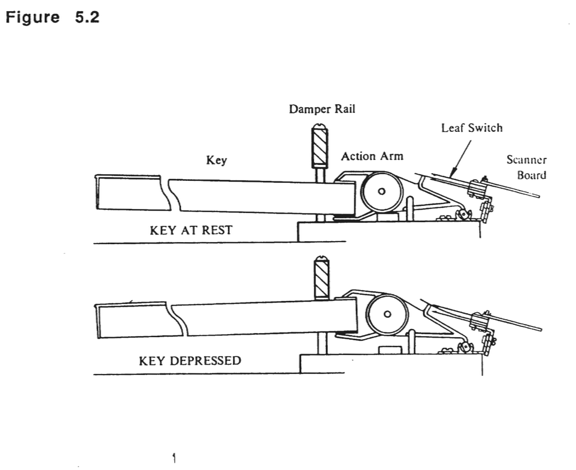
To install a Keyswitch board assembly, insert the screws in the holes in the mounting bracket on the action assembly. Then slide the Keyswitch board assembly down over the screws. Slightly tighten the screws at the far ends first, then the two screws in the center. Do not tighten the screws completely at first. Simply tighten so that the assembly will slide up or down with slight pressure. Align one side .01 inch from the tab. Tighten and align the otherside. Then align the middle of the assembly and tighten. This should give a rough alignment. The longest leaf of the switch should be no more than .01 inch from the black tab on the action arm. The longest leaf must be touching the bottom leaf, and you can visually verify that this is correct by pressing a key and watching when it is released to be sure whether the bottom leaf moves when the longest leaf returns.
Figure 5.2
5.4 - MOD LEVERS
5.4.1 - Accessing the Mod Levers
The Mod Levers are mounted under the top enclosure and are connected to the Slider board on the Front Panel assembly by a cable.
Follow the previously described procedure for disconnecting the top and bottom enclosure. The Mod Levers are held by the shafts of their rotary potentiometers. The potentiometers are held in place by a single nut with a lock and play washer.
5.4.2 - Removing the Mod Lever Pots
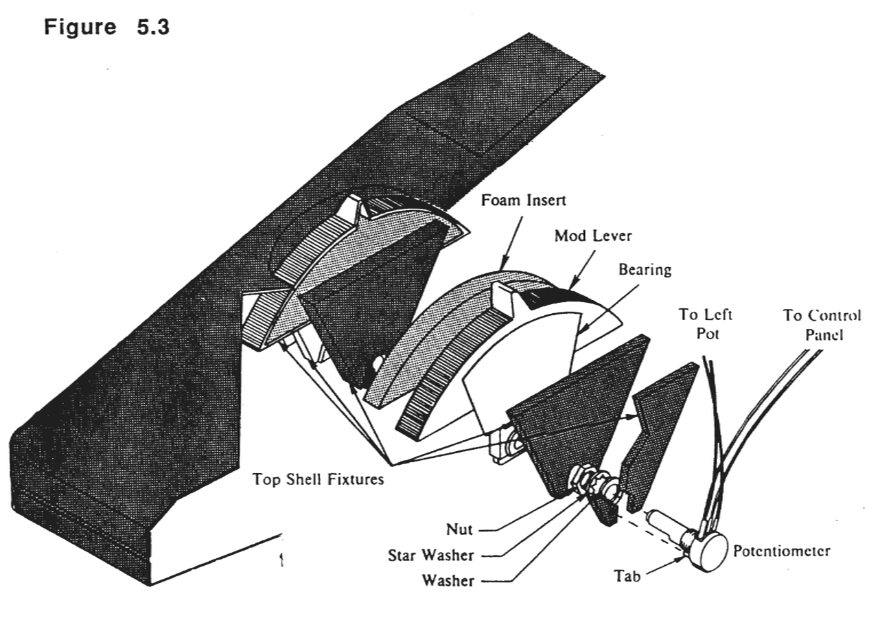
To remove the Mod Lever pots, it will require a thin 1/2 inch open end wrench. A positioning tab keeps the potentiometers from rotating. This tab is aligned with a hole in the side of the enclosure rib where the pot is mounted.
Figure 5.3
5.4.3 - Calibrating the Mod Levers
On new instruments, Mod Levers are calibrated at the factory and do not need any adjustment in the field. If you replace the Mod Levers or the Slider board, then the Mod Levers must be re-calibrated.
The steps are:
- 1. Put the instrument in its default settings, preferably with battery-backed memory cleared.
- 2. Turn the power off and open up the Front Panel.
- 3. Turn the power back on, leaving the Front Panel in its service position.
- 4. Turn the LOWER trimpot on the Slider board while hitting a piano note and listening to the pitch.
- 5. Listen for the "dead band" where the pitch of the piano note is constant and center the trimpot in that range.
- 6. Now enable Assignable control 1 (vibrato rate) and move the Assignable slider 1 to mid-scale (34Hz vibrato).
- 7. Adjust the UPPER trimpot to minimize the amount of vibrato with the right Mod Lever at rest position.
5.5 - KURZWEIL 250X
5.5.1 - Kurzweil 250X Enclosure
The Kurzweil 250X cabinet enclosure unlike the K250 is a single piece. No portion of the Kurzweil 250X cabinet enclosure is removable. Please follow the procedures described for the K250 model for board removal.
5.6 - KURZWEIL RMX 250 AND 225
The RMX enclosure consists of an outer and inner enclosure. Before you begin to service the unit, please remove the unit from any rack assembly or enclosure it may be mounted in.
5.6.1 - Front Panel Assembly
Accessing the Front Panel Assembly
With this procedure you can reach and remove the two boards mounted on the Front Panel assembly and gain access to the inner chassis enclosure. Remove the 4 hex nuts from the rack ears. Slide the inner chassis enclosure towards you. You may do this by either separating the unit at the rack ears or by pushing on the rear panel.
Remove the Front Panel Assembly by doing the following:
1. remove the 2 phillips head screws from each side of the assembly, 2. remove the 3 phillips head screws from the bottom (underside) of the assembly, 3. disconnect the flat ribbon cable from the Channel to the Control Panel board (J02) and the flat ribbon cable from the CPU to the Control Panel board (J37). 4. place the Front Panel assembly on foam or safely aside so that no harm is done to the slidepots as they are fragile.
5.6.2 - Inner Chassis Assembly
To gain access to the inner chassis assembly follow the instructions described above to remove the Front Panel assembly. Once the Front Panel assembly has been removed turn the unit on its side. Remove 3 phillips head screws from each slide on the bottom of the inner chassis. Turn the unit back to its normal position and remove the inner chassis. Remove the outer chassis safely out of your work area.
The illustration below shows a side view of the p.c. board placement in the RMX inner chassis.
Figure 5.4

5.6.3 - CPU Board
To remove the CPU board, it is necessary to disconnect all cables connected to the CPU. There are 3 flat ribbon cables to be removed: 1 from the CGP board, one from the Channel board and one ribbon cable that connects the CPU to the Front Panel board. Next, remove the two brown power connectors and the MIDI cable located next to the rear panel on the CPU. Now it is necessary to remove the 4 fastening nuts securing the four 1/4 inch phone jacks to the rear panel. Then remove the 13 phillips head screws which mount the CPU to the inner chassis.
5.6.4 - Replacing RMX Engine EPROMs
Remove the 4 phillips head screws from each side of the shelf containing the Channel board. Lift the shelf slightly. You will not be able to use an EPROM puller as there is not enough clearance. You can use a long thin flat head screwdriver. Please be careful not to damage p.c. board or sockets while doing this.
5.6.5 - CGP Board
To remove the CGP board, it will be necessary to remove 6 cables. Two from the CGP board to the Channel board, two from the CGP board to the CPU board, one from the power connector to the CGP board and one long flat ribbon cable that from the CPU to the Channel board. Once the cables have been disconnected, remove the 13 phillips head screws holding the CGP to the chassis.
5.6.6 - Power Supply Assembly
The Power Supply board is attached to the Channel Board on the inner shelf and is enclosed in a metal shield. Depending on the repair you are performing it may or may not be necessary to remove the top portion of the Power Supply enclosure. If you are replacing the Power Supply board, it will be necessary to remove the 6 phillips head screws securing the top enclosure, disconnect the wire terminals going to the Power Supply board from the interal harness cable and then remove the 7 phillips head screws securing the Power Supply board to the bottom portion of the enclosure (see Chapter 7 for RMX Wiring Diagram).
5.6.7 - Channel Board
To remove the Channel board, it will be necessary to remove the Power Supply enclosure and the following cables: 1 from the Audio board to the Channel board, 1 from the power supply to the Channel board, 1 coming from the Control Panel board to the Channel board, 1 coming from the CPU to the Channel Board and 1 coming from the CRT to the Channel board. It is not always necessary to remove the shield. However, if you are replacing the Channel board, be sure that the shield is out on the replacement. Once the cables have been disconnected, remove the 8 remaining Phillips head screws holding the Channel to the inner chassis shelf.
5.6.8 - Audio Board
To remove the Audio board, simply disconnect the ribbon cable from the Audio board to the Channel board. Next, remove all hardware securing it to the rear panel.